Making of a Spatha
Design
The Spatha sword we constructed was made using methods similar to the Roman blacksmiths during second century AD. Although the construction was similar to the construction during the Roman times, the tools we used to create the sword are of modern technology due to our short time frame. The replica Spatha is based on the Lauriacum-Hromowka sword which is a straight bladed sword with a small triangular tip. The dimensions used for the replica are from a Spatha found, from late second to third century AD [104]. Below is a Solidworks CAD drawing for the replica Spatha blade.

Figure 1. CAD Model of Replica Sword.
The blade will consist of three metal plated stacked or laminated together. The outer plates will be made from low carbon 1018 steel, classed with iron, and the center plate will be of high carbon 1075 steel. The order of the plates can be seen in Figure 2, with the light colored plates representing the iron (1018 steel) and the darker plate representing the high carbon steel (1075 steel).
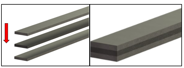
Figure 2. Order of Steel Laminations.
The use of the different plates allows the blade to have hard sharp edges, but still have the toughness needed upon impact. The high carbon steel in the center of the blade is what will provide the hard edges of the blade and the iron will provide the toughness. If the entire blade was made from high carbon steel, the blade would be brittle and therefore be likely to break during use.
Blade Creation
Before any hammering could take place, we needed to turn the three separate plates of metal into one, properly sized piece. The starting width of the plates needed to be around 3.75cm (1.5in) wide. Only the 1018 steel was available at this width. The 1075 steel that was purchased was about 5cm (2in) wide and needed to be cut down to match the size of the 1018. This could have been done using a saw, but the high carbon concentration of the 1075 steel makes it very hard to cut. One option would be to use a specialized bandsaw blade made for high carbon steel. Unfortunately, the manufacturing labs at WPI did not have this type of blade. Instead, a plasma cutter was used to make quick work of cutting the steel. Plasma cutters are able to cut through electrically conductive materials by directing an accelerated jet of hot plasma into the material. The 5cm wide 1075 steel was clamped to the work surface with the 1018 steel on top acting as a guide, insuring a straight cut. This procedure can be seen in Figure 3.
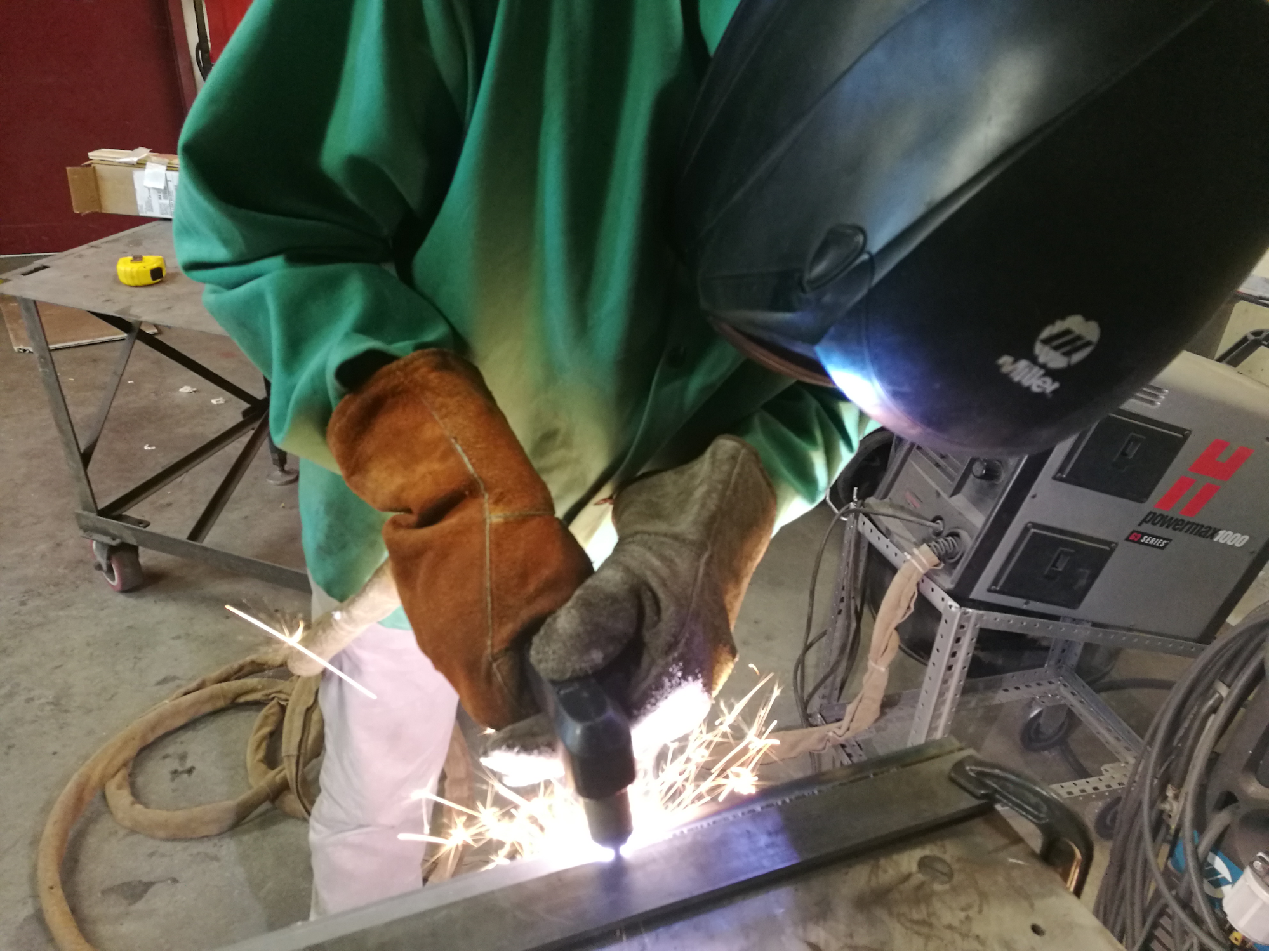
Figure 3. (a) Original Plate of 1075 Steel and (b) Plasma Cutting the 1075 to the Proper Width.
After the different plates were at the same widths, they had to be cut to the same lengths. The process used to cut each plate into about 30cm (12in) long pieces using a chop saw, as seen in Figure 4.
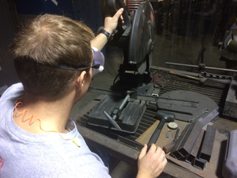
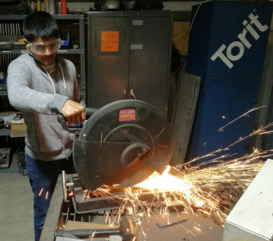
Figure 4. (a) Aligning Metal to be Cut and (b) Cutting Metals to the Proper Lengths.
In addition to cutting the steel into 30cm plates, we also used the saw to cut small blocks off of the raw stock. We cut one piece from one of the 1018 plates, and another from the 1075 plate. We brought these two pieces back to Washburn, where we removed a chunk of the 1075 that had been affected by the plasma cutting process. We then used the bandsaw to cut the 1018 sample and the remainder of the 1075 sample into three different pieces each, exposing all three faces of the samples. Finally, we ground down the edges & faces of the samples to remove any burrs and sharp edges that were present. These were samples of the original materials which were reserved for later analysis.
Once the metal for the actual blade was the right size, we used a hand-grinder to smooth off the faces of all three pieces. This process, as seen below in Figure 5, is important for the binding of the metals when we start heating them up. Scratches or bumps on the faces would result in bubbles or warping when the metal was heated and bound to each other.
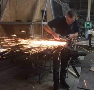
Figure 5. Hand Grinding of The Sheets.
Once all three were cleaned off, we welded them together so that they would stay aligned with each other when it came time to heat. We also welded on a long steel rod to one end of our stack, as seen in Figure 6. This provided us a grip with which to handle the metal while it heated in the furnace.
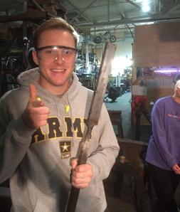
Figure 6. Three Sheets Welded Together and Attached to Temporary Steel Handle.
Our metal was now ready to work, so we fired up our furnace. We could have created a historicly accurate blast furnace, but we decided to use a propane furnace, as seen in Figure 7, which was much more straightforward. Once the metal started to glow, we sprinkled borax powder over it as seen in Figure 8. This process was repeated a few times, giving the borax a chance to melt and adhere to the metal before adding more. The purpose of the borax is to help flux the metals. This prevents oxidation as the different metals are forged together.
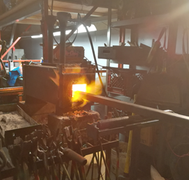
Figure 7. Propane Furnace.
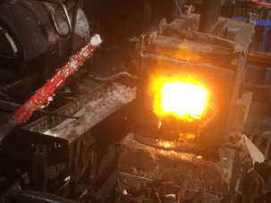
Figure 8. Adding Flux to the Hot Metal.
Shaping
With the metal properly heated and fluxed, we began pressing and stretching the metal into the dimensions we needed. For the majority of this process, we utilized a powerful hydraulic press to compress the metal, as seen in Figure 9. Most of the pressing involved putting the metal in the machine flat, but because pressing elongates both the metal’s length and width, we also pressed the thin side to prevent it from surpassing our desired width. We also used a hammer and anvil to reshape the metal as shown in Figure 10. This was mostly for straightening the metal when it got oddly bent, but also so that we could get a taste of how it would be done in ancient times.
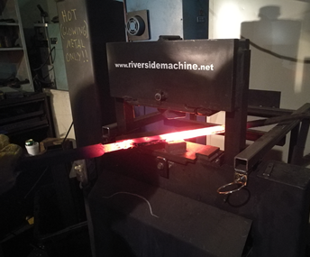
Figure 9. Pneumatic Press Used for Stretching Metal.
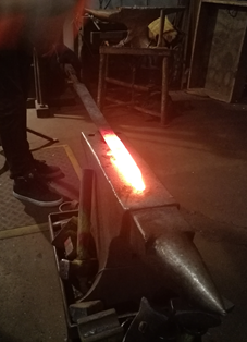
Figure 10. Hammering Sword on Anvil.
After we finished pressing our metal, it had been stretched from 3.75cm by 30cm (1.5in by 12in), and 2cm (0.75in) thick, to 5cm by 68.5cm (2in by 27in) and 0.6cm (0.25in) thick. From there, we hammered out the sword’s tip by resting the hot metal at an angle on the anvil and striking the end, as depicted in Figure 11. It is also possible to for the tip by stretching the metal even longer and grinding down a point, but we decided that would take too long, as grinding is such a slow process. Once the point was made, we began to develop the edges of the blade. By angling the blade and hammering inward, we sloped the sides of the metal. Doing this on both sides created the blade of the word, creating the hexagonal shape of the sword seen in Figure 12.
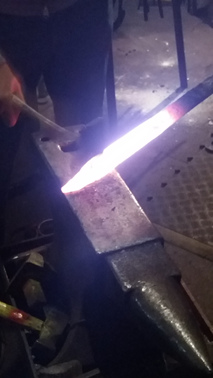
Figure 11. Hammering the Point.
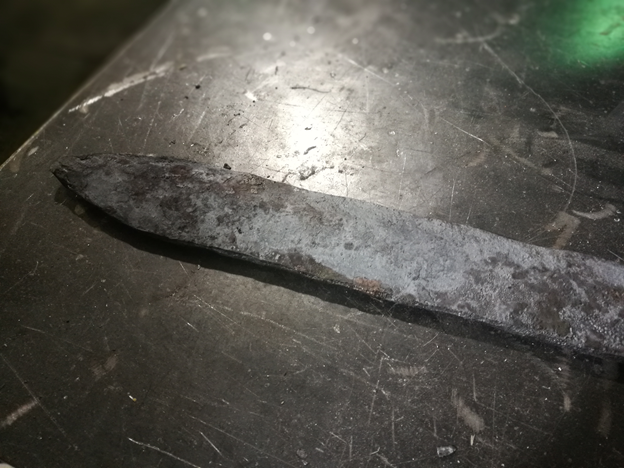
Figure 12. Sword After Hammering Edges.
With the body of the blade stretched and shaped to our liking, we began work on the tang. This is the short metal bit that extends from the base of the sword which will be surrounded by the handle. We removed the handle that we had welded on to help with forging. After, we marked off about 5cm from the base of the blade. From there, we use the clamp-like tool seen in Figure 13, to hold down the metal at the marked off length.
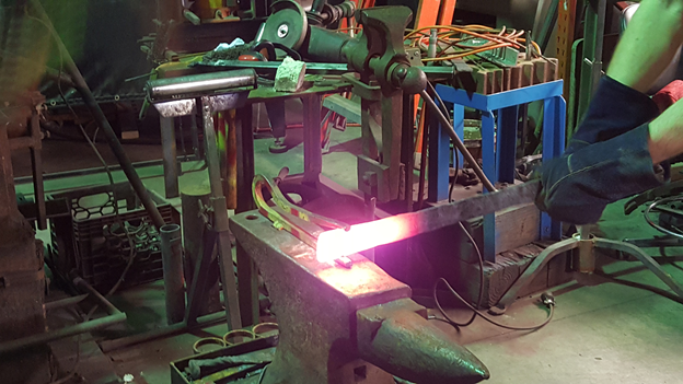
Figure 13. Creating the Tang.
The tool was then hammered to create dents in the blade at the point we had marked. The metal had to be very hot to prevent the sword from splitting, so we could only do a few hits at a time before reheating. Eventually, the dents were big enough that we could begin hammering them into the tang. Using both hammers and the press, we flattened out the tang to complete the forging of our sword, as seen in Figure 14.
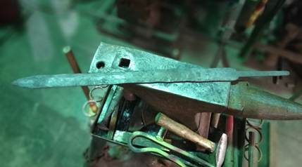
Figure 14. Forging Process Complete.
Grinding
After the sword had cooled off, we began the final grinding phase. We first used the handheld 4.5” angle grinder from the beginning of the project to go over the metal and remove all the scale (iron oxide), as seen in Figure 15. It was important to clear off these patches of scale, because they would cause premature wear of the belt sander belts. However, the hand grinder was not as consistent as the belt sander and it would have been much more difficult to grind the sword’s edges down to a blade. After the rough edges had been removed, we moved on to belt grinding.
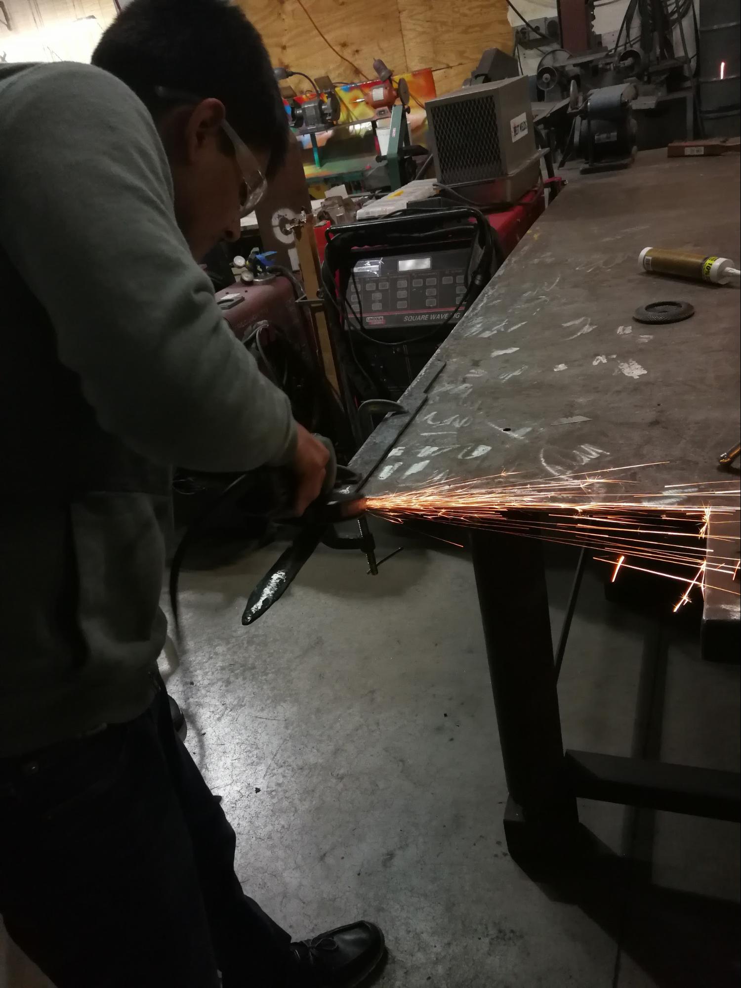
Figure 15. Grinding off Iron Oxide.
Using the Belt grinder we were able to smooth down the edges of the sword. We used lower grits to quickly shape the blade and then worked our way up in grit to get a nice smooth finish. The belt sander had an attachment that held the belt flat against a metal backing plate. This allowed the edge of the sword to be straightened along its length, seen in Figure 16a. The flat section of the belt was also used to flatten the sides of the blade and create the bevels. Once the rough outline of the final shape was created the top section of the belt sander was used to round the surface to the edges of the blade, seen in Figure 16.
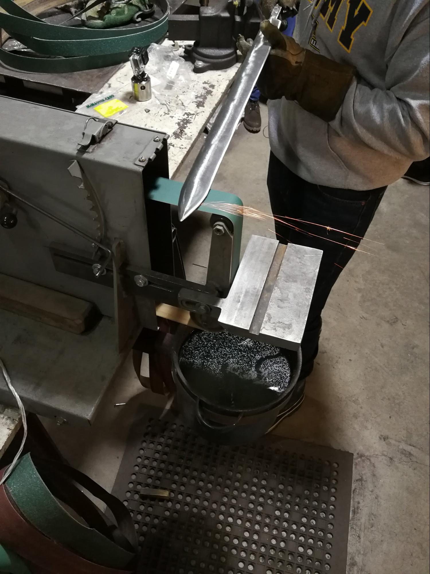
Figure 16. Straightening Blade Edge.
The last step that needed to be done to the blade was to shape the tang. This was done to provide a flat and square surface for the guard to sit against. A file guide was clamped on to the blade to help with the filling accuracy, seen in Figure 17. Once the material above the guide was removed the swords blade was complete.
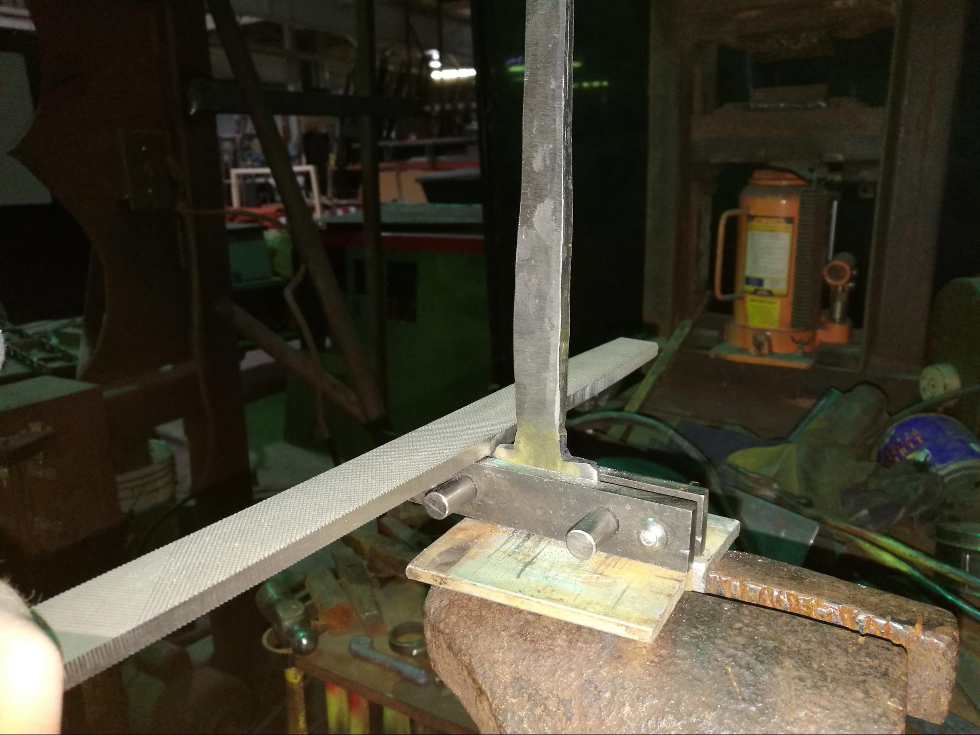
Figure 17. Filing Tang using File Guide.
Handle Creation and Assembly
Next up was to create the handle. The Roman Spatha hilt was comprised of a guard plate, a guard, a grip and a pommell. The design for our replica Spatha was created using similar dimensions to several roman swords that have been found. The guard plate would be manufactured out of Brass and the hilt components out of Hard Maple wood. The hard Maple wood for the Hilt was purchased as a 3” x 3” x 12” block. We used power tools to cut our block of wood into 3 separate pieces.
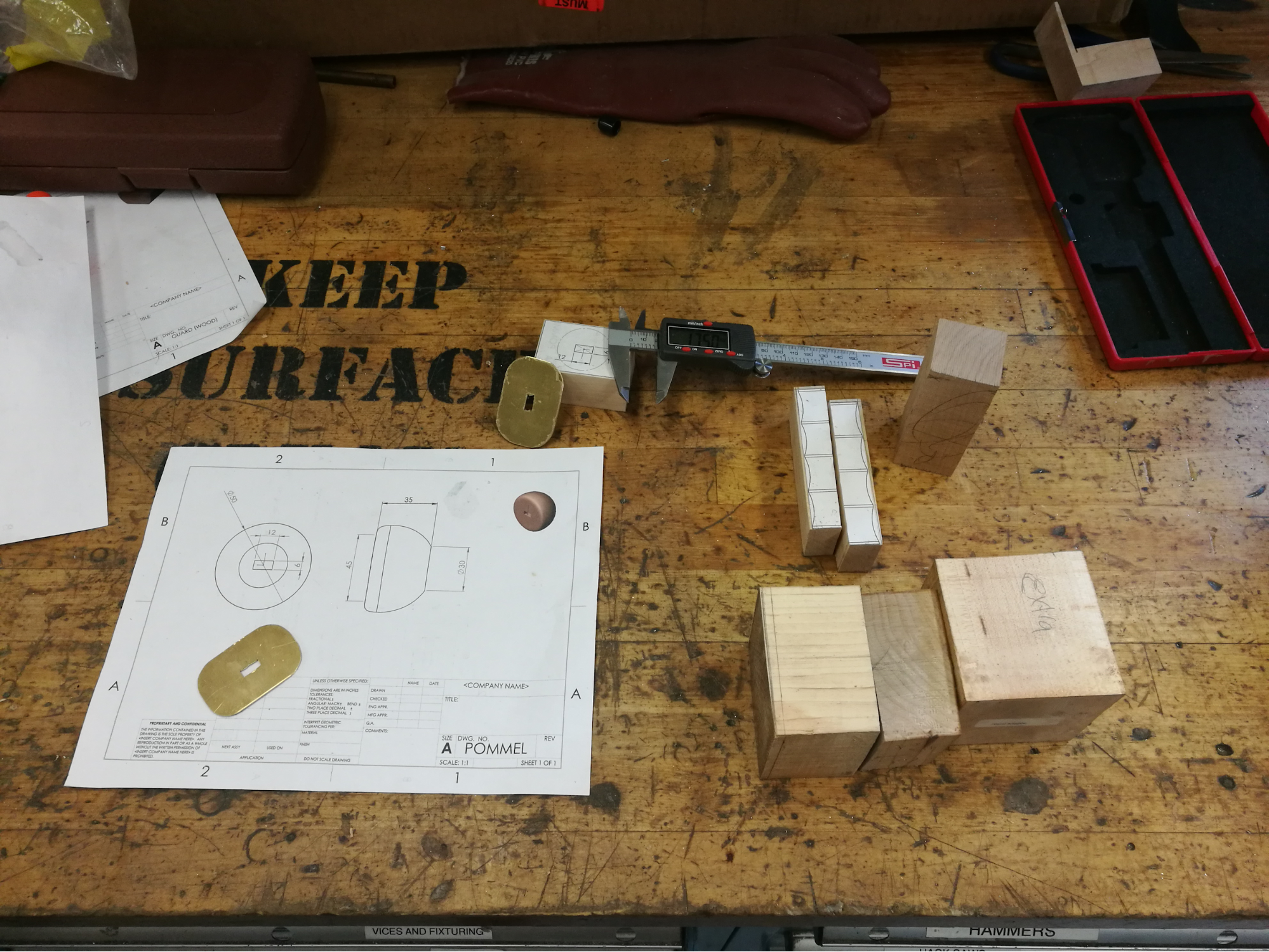
Figure 18. Grip cut down center.
We used chisels and grinders to shape down the blocks of wood to their rough shapes, and then drilled a hole through them with a milling machine to make room for the sword tang. The handle had to be cut in half in order to get a good hole through the middle because it was too long to cut a full hole through with the milling machine. We used glue to put the pieces back together, seen in Figure 19. Lastly, the guard was sanded into its final shape using a belt sander to create the rough profile and then hand sanding to clean and smooth the edges. The test fitting of the Hilt components can be seen in figure 20.
Figure 19. Handle, Pommel and Guard After Sanding.
Figure 20. Test Fitting of Hilt Components.
The last components of the Hilt to be created was the Brass guard plate and the pommel washer. Using the CAD model drawings as templates the dimensions were transferred to a 0.05in thick sheet of Brass. A hand saw was used to cut the rough profile because of the small size. After most of the material was removed, we used sandpaper to smooth down the outside of the guard to a nice final form. The rectangular tang hole through the center of the plate and washer was made by drilling three small holes, side by side, and then finishing using small metal files. All of the completed Hilt components can be seen in figure 21.
Figure 21. Finished Hilt Components.
Before assembling the Hilt for our Spatha replica the wood was stained and then sealed using polyurethane. The stained and sealed Hilt components can be seen in Figure 22.
Figure 22. Stained Hilt Parts.
The proper assembly of the hilt components uses the tension of the peened tang to hold the components together. Due to a large amount of tolerance in the channels the Grip and Pommel had a loose fit between these components and the blades tang. To solve this issue a two part epoxy was used to fill the gap.
The final step needed to complete the sword is to install the pommell washer and peen the tang. By leaving the tang slightly longer than all the components it is allowed to protrude through the brass washer. This small amount of steel is then struck many times to displace the material over the washer. The before and after peening of the tang can be seen in Figures 23 and 24.
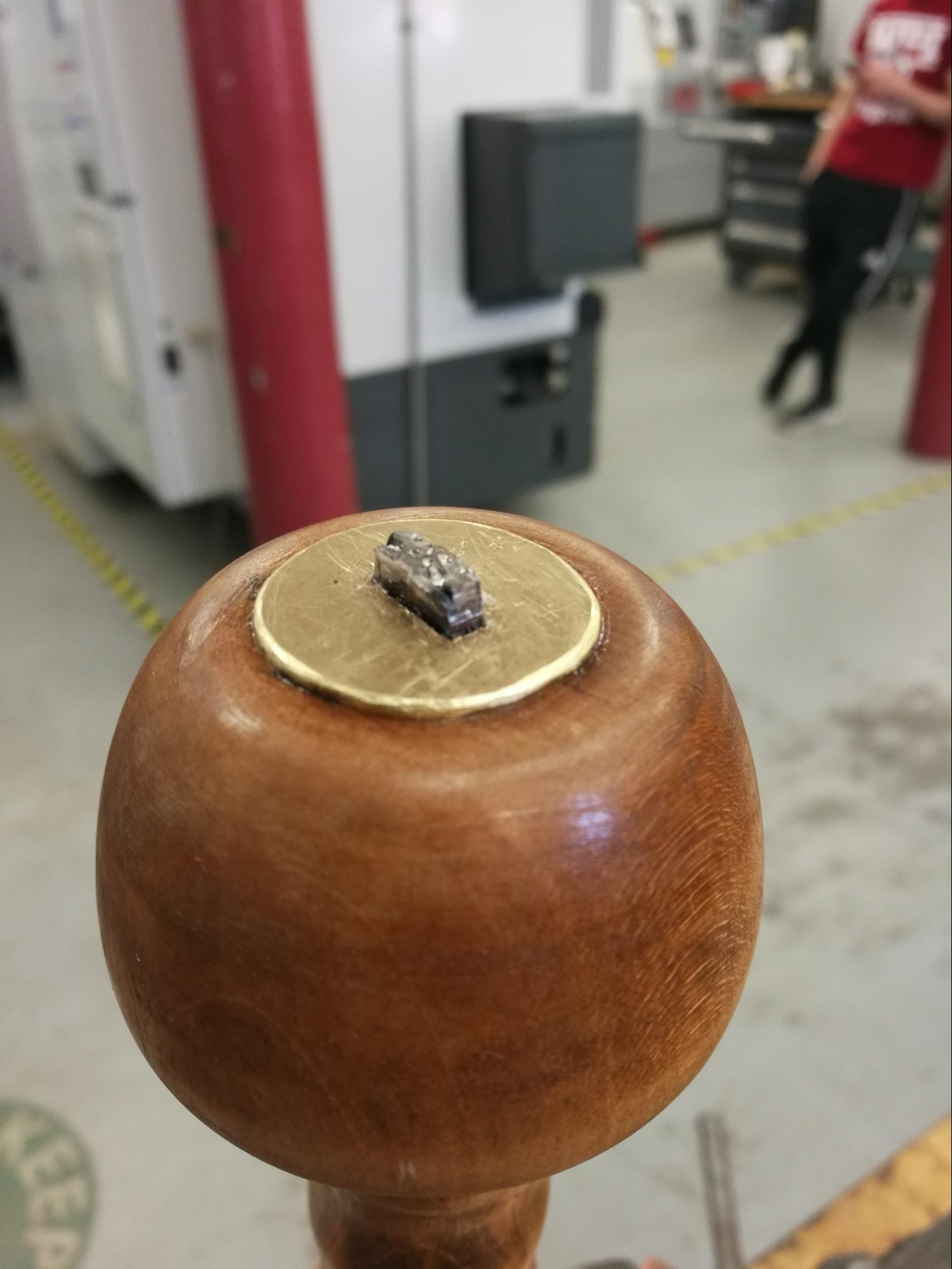
Figure 23. Before Peening the Tang.
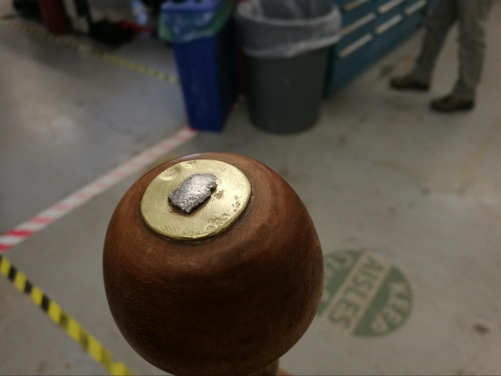
Figure 24. After Peening the Tang.
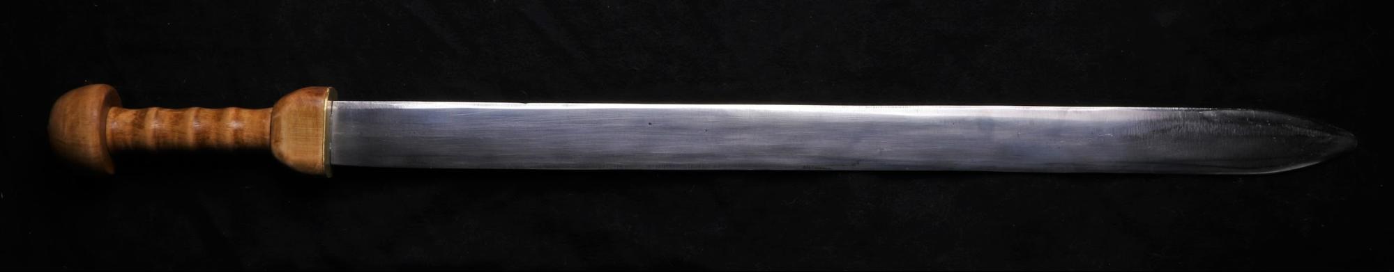
Final Product