Making of a Falcata
Overview
This page presents the manufactural steps used in creating a replica falcata.
Planning
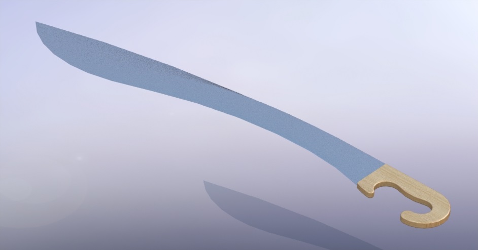
To properly plan out the forging strategy, it was essential to draw out a design. A render (Figure 1) was developed utilizing CAD software to visualize the replica sword, and have a solid idea about its dimensions.
 |
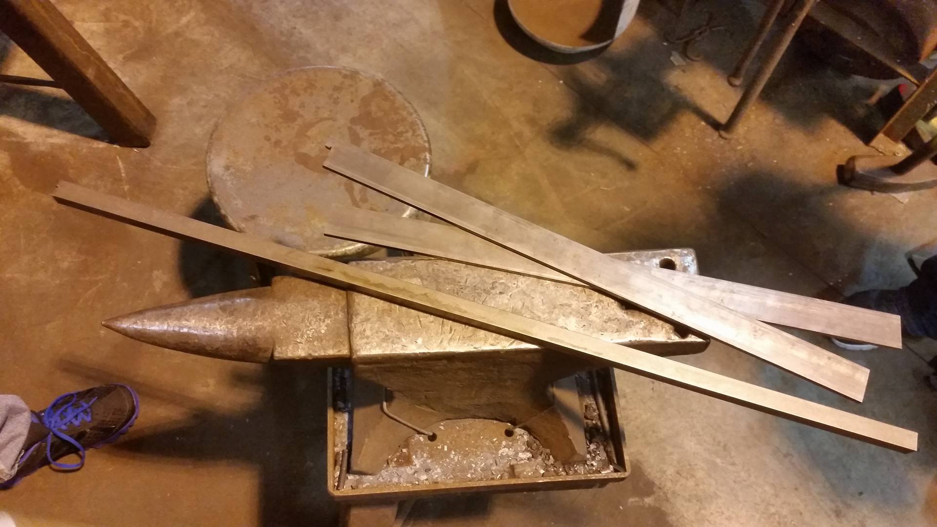
Through research, it was also determined that these swords typically had a harder steel sandwiched in between two softer steels, so in preparation three pieces of metal were purchased (Figure 2): 2x 10¹⁸ steel (0.18wt% carbon) 2ft by 1.25in by 0.25in and 1x 1045 steel (0.45wt% carbon) 4ft by 0.75in by 0.75in. This harder, longer bar was larger than was needed, and not the ideal dimensions, but was all that was available.
 |
Lamination
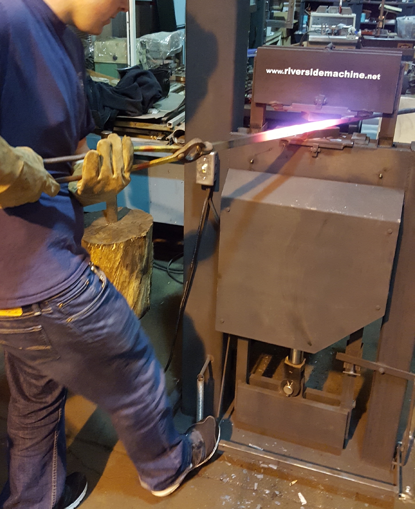
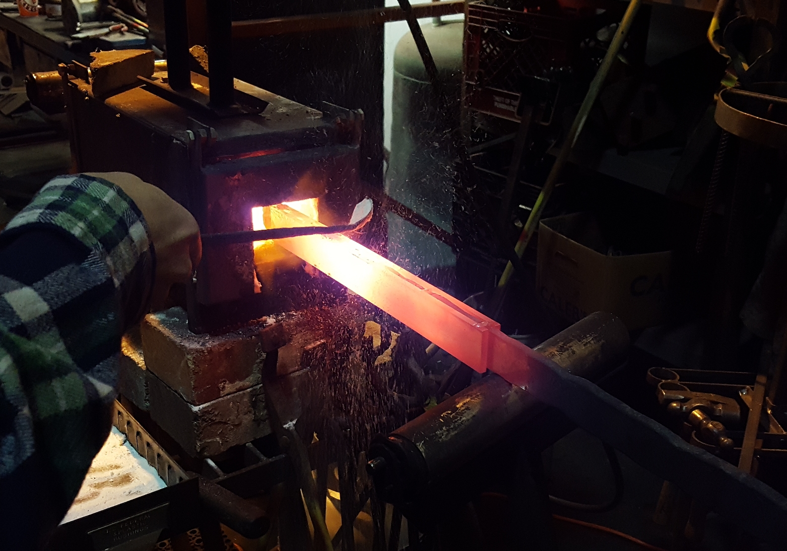
As a preparation step needed before the lamination of the different metals into the sandwich configuration, the thick 1045 square bar needed to be flattened and widened. The hydraulic press was used to complete this task (Figure 3). The majority of that bar was brought down to roughly the dimensions of the other two pieces of metal (aside from the length). The metal was heated up before each sequence of pressings using a propane forge (same heating method used for all forging steps herein).
 |
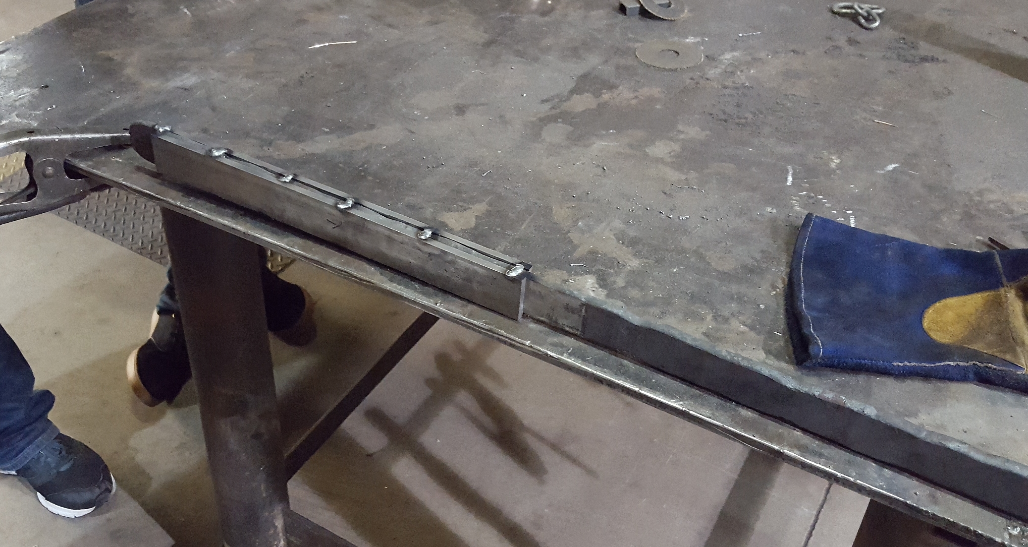
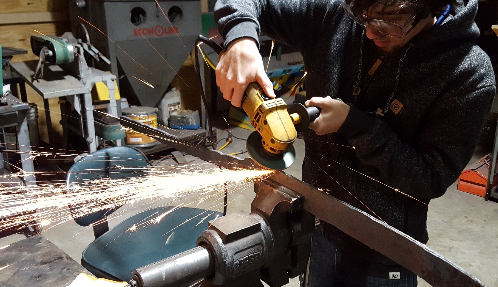
After the 1045 bar had the correct dimensions, the faces of that bar were grinded down using a handheld grind-wheel to remove the scale that had built up from forging. All the faces that would be bonded together during the lamination process (on all three bars) were carefully cleaned and flattened using this grinder, so that as few material imperfections existed where the forge-welding bond would be created. After the faces were clean, they were aligned and the edges were tack-welded so the sandwich would hold together until after the lamination process (Figure 4). The extra length available on the (middle) 1045 bar was used as a convenient place to hold during the remainder of the forging process.
 |
To start the lamination, the 1018-1045-1018 sandwich was heated up as possible in the propane forge, then sections of that was compressed down using the hydraulic press (Figure 5). As soon as the metal started to lose a bit of its glow, it was sent back to the propane forge to regain heat, so the metal was as hot as possible at all times. In order to reduce oxidation between the metal (limiting the strength of the bond) a forging flux was used to displace the oxygen until the metal was bonded. The forging flux used was called borax, and had no chemical effects on the metal itself. This powder substance was poured over boundaries between each layer of the metal sandwich once each heat cycle (Figure 6).
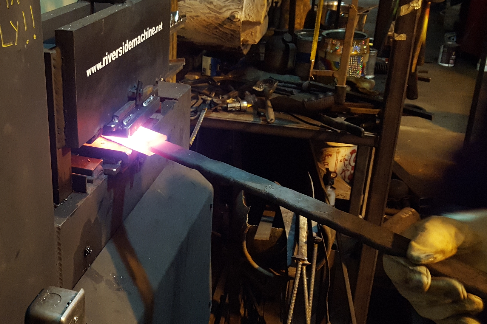 |
 |
After the lamination was started all throughout the layered region, the bar was cool slowly and then brought back to the grind-wheel. The boundary of the bonds were ground heavily until no cracks were left present (Figure 7), in order to reduce the amount of present divisions so it was unlikely to split later in the forging process.
 |
With the laminate confirmed to be as good as can be, the bar was taken back to the forge and was made to be more consistently rectangular and uniform in its dimensions. The far end of the laminate region was then cut off at an angle (Figure 8) so less forging was needed to make the tip of the sword.
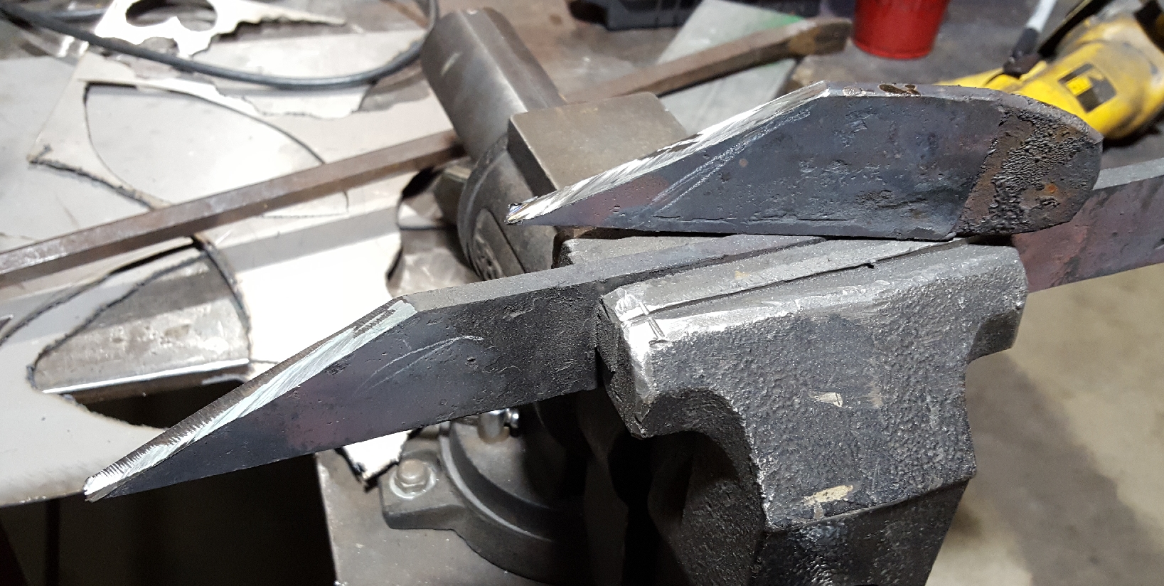 |
Shaping
The first part of the shaping process for the sword was to counteract the bending that would occur when an edge is put onto the blade. This involved simply hitting the blade where it was not directly supported by the anvil from the back, creating a bend opposite to what the final sword would have (Figure 9).
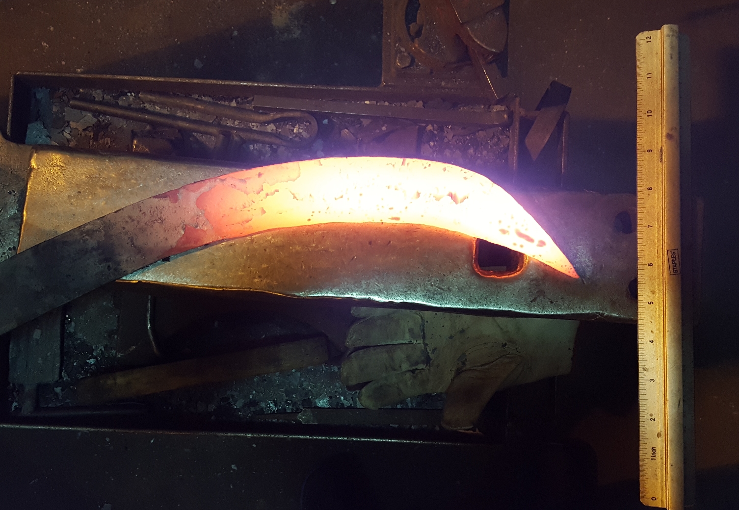 |
With the counteractive bend in place, the next step was to stretch out the far end of the blade into a wedge-shaped edge. The design called for as much width here as possible. Using a cross peen hammer (rather than a typical at faced hammer) we were able to stretch the sword along its width, making sure not to make anywhere too thin (~1/16in). The blade was widened as much as possible in this region (Figure 10). Additional work similar to this was done to make the rest of the blade take the appropriate shape according to the CAD model, and make sure the curves of the blade were smooth and continuous.
 |
After the blade was forged to its final shape, the last bit on the sword to shape was the tang. Before this could be reached, excess material needed to be cut off on either end. Before the work on the tang, that region had the same dimensions everything had after the lamination (rectangular) so a round space for the hand needed to be made, and the tang needed to be long enough to allow a full hand to fit inside that space comfortably. To do this, a teamwork process of holding, hitting, and guiding was employed (Figure 11) to create the shape desired quickly and carefully.
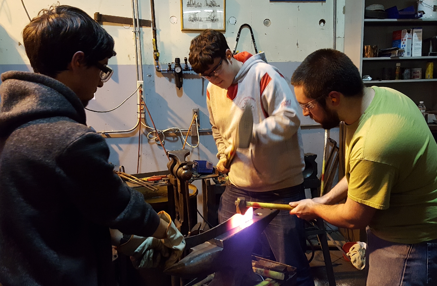 |
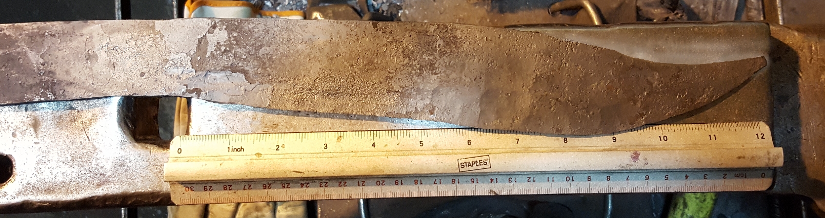
With the shaping of the tang completed, the forging part of the sword's creation was completed. The final shape of the sword at this stage (Figure 12) was basically the final shape, but a bit larger so some material could be removed during cleaning.
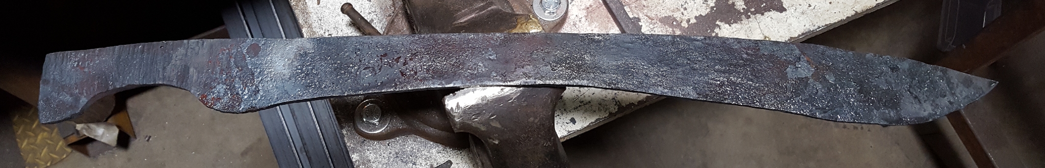 |
Grinding and Creating the Handle
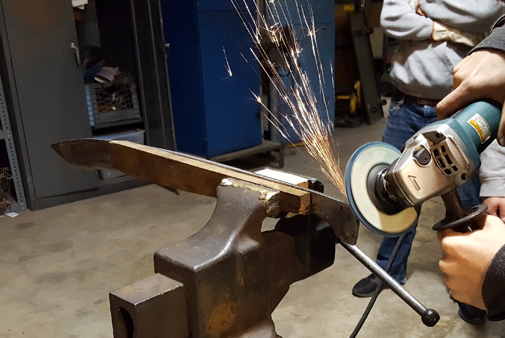
The next step after forging was to grind away the scale and imperfections of the blade, in order to create a clean surface for the blade in the shape of the final sword. This involved a lot of work with the grind-wheel, and involved cleaning both the faces of the blade and the edges/contours of the blade (Figure 13, 15).
 |
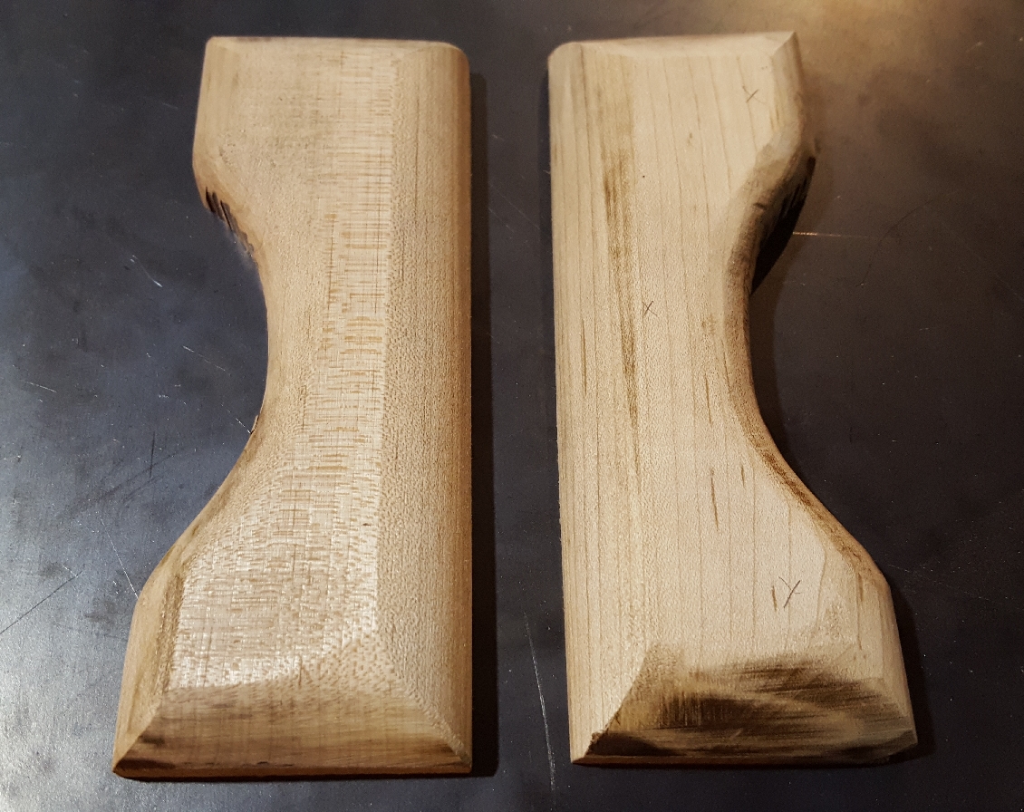
Prep work for the wooden part of the handle was done simultaneously with the grinding processes. Utilizing pieces of previously-cut maple, the halves of the handle were cut to the correct approximate size using a band saw. The shape was further refined and rounded using a belt sander. The two rough halves of the handle (Figure 14) were made to be slightly larger than the tang that they would sandwich, since the wood was easier to shape than the metal.
 |
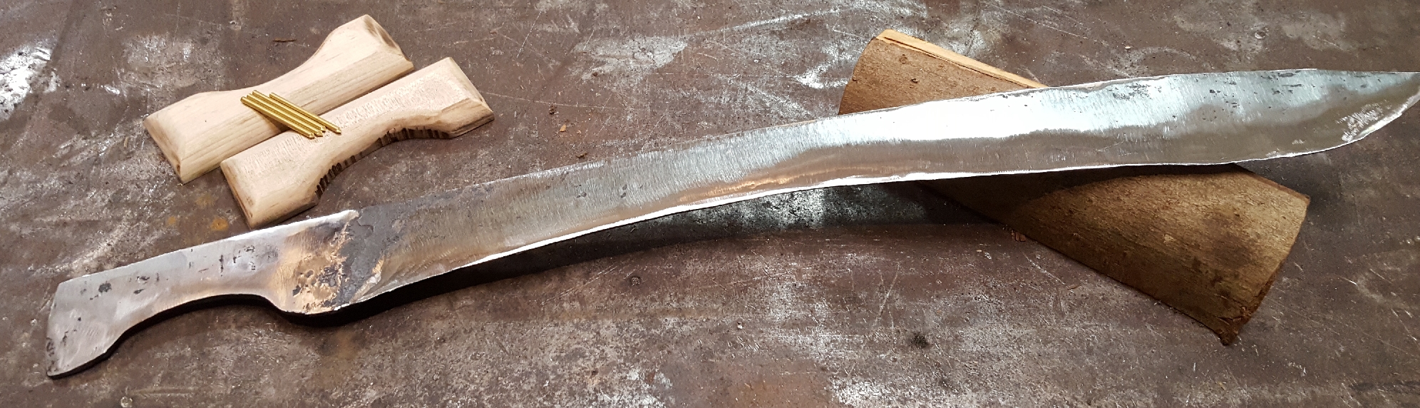
Brass 1/8in pins were also prepared to be longer than the total width of the handle, and when the blade was mostly grinded down (Figure 15) and the rough wooden handle halves were prepared, the holes were ready to be drilled into the wood and the tang.
 |
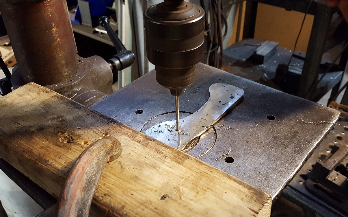
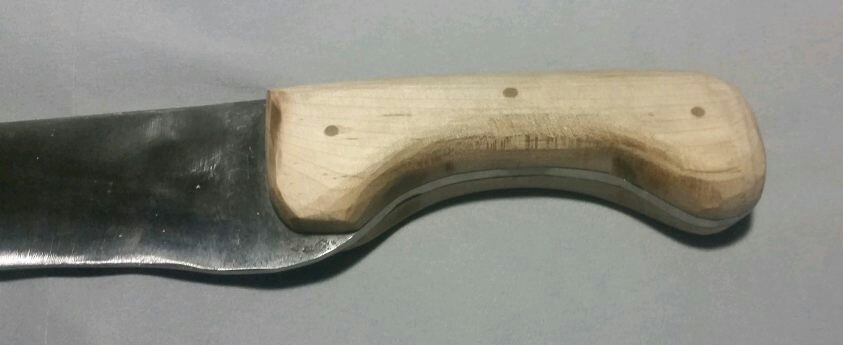
A slighly larger drill bit was used to drill into the metal first in three places (Figure 16), and then a slightly smaller drill bit was used to drill into the wood (one handle half at a time) using the tang's holes as a guide. Extensive care was given to ensure the holes lined up perfectly, and that the pins would not split the maple.
 |
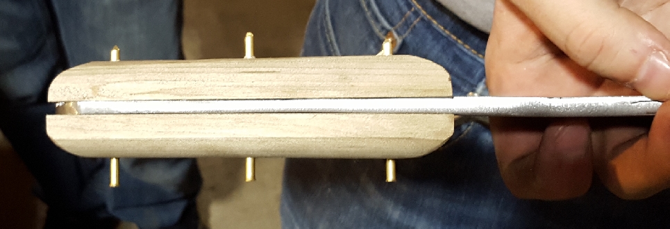
After all three holes were drilled, the pins, with pointened ends, were gently hammered through the wood-tang-wood sandwich (Figure 17), and solidified the handle in place. After these pins were trimmed down to the surface of the wood, the finishing touches on grinding the blade was done.
 |
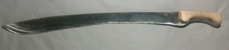
After the blade's finishing touches were complete, the handle was sanded into its final rounded shape (Figure 18) using a belt sander. The surfaces of the tang and the wood were made to be continous with each other by sanding down the wood to be tangent to the tang.
 |
With the handle complete, the sword was finished (Figure 19).
 |