Making of Armor
Our group tried to make the shoulder guards of an European armor using traditional hand tools like hammers, shears and files. During the middle ages, blacksmiths had similar tools but they were probably bigger, heavier and less ergonomic.
Steps for armor making
Before making the armor, we drew the different components of the shoulder guards on paper. The measurements we used were in inches and the drawings are as follows:
| Part | Drawing |
|---|---|
| A | 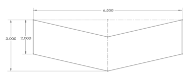 |
| B | 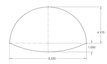 |
| C/D | 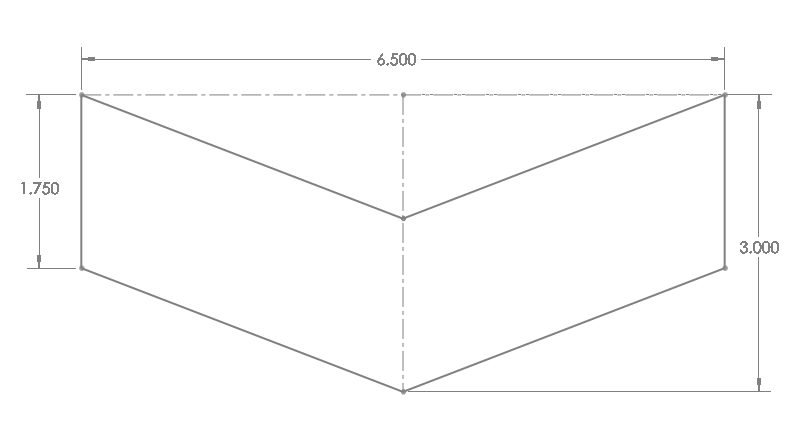 |
Figure 1: Drawings of shoulder components
Using the paper as stencil, we then drew the outline of the paper on a sheet of metal. The metal sheet that we used was made of steel containing around three to four percent carbon.
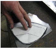
Figure 2: Tracing of Shoulder Components on Metal Sheet
Once the outlines are drawn on the metals, we used shears to cut the different pieces of the shoulder guards. We used shears with different cutting angles; when we used the right most shear in the picture, we had to leave a gap between the pencil line and where we were cutting as the curvature of the cut tends to be more inwards.
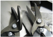
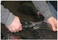
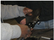
Figure 3: Cutting of metal pieces with shears
After cutting, we used a file to smooth the edges and get rid of the dangerous sharp edges. According to Fay Butler, blacksmiths would take a quite thick and hard piece of steel and upset its surface in a consistent pattern using a sharp object like a chisel. After the dents were made at a certain angle, the surface of the metal would become irregular and it would have some small projections or teeth. The piece of metal would then be soaked in horse urine. The effect of the acid in the urine would sharpen the small projections on the metal surface sharper and give the metal surface an abrasive effect.
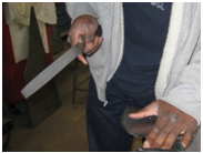
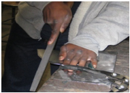
Figure 4: Filing of metal pieces
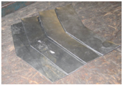
Figure 5: Cut pieces
After cutting and filing, the next step was to give the different pieces of the shoulder guards a curvature. For this purpose a hammer and a piece of metal block with a smooth surface were used.
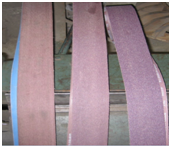
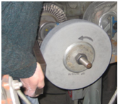
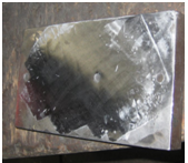
Figure 6: Abrasion process
The diameter of the hammer head is also important because it will determine the curvature of the metal piece after hammering. Since one of our hammers was a too flat (left most in the pictures below), Fay Butler adjusted it by using an abrasive to change modify the edges and hence change the diameter of the hammer. In the right picture, a lot of sparks are coming out of hammer under abrasion and this is because of the carbon content in the steel of the hammer. Steels with higher carbon content tend to produce more and shorter sparks under abrasion.
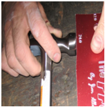
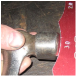
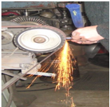
Figure 7: Changing of hammer head radius
The picture below shows the filings of the hammer after the abrasion process. The filings from our hammer are very small and dust like because the abrasive material that we used had small and sharp teeth. The bigger filings shown in the picture below come from another piece of metal from which a greater layer of metal was taken off and a bigger teeth abrasive material was used.
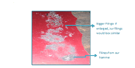
Figure 8: Metal filings
To get a slightly dome shaped of part A and smooth finish we hammered it to bend the metal. This process only involves folding the metal. When hammering, a lot of pressure has to be applied in the center of the piece and less pressure on the outer edges like shown below. This step is then repeated for the other remaining identical parts.
The hardest part of the shoulder was to get a dome shape out of Part B which looks like half circle. This process involves shaping and the folding of the metal sheet. The first step was to make a tuck in the metal using the straight peen hammer like shown below. The tuck that we made was about one third of the length of the metal piece.
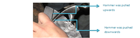
Figure 9: Making of a tuck
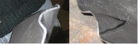
Figure 10: Tucks
After the tuck was made, we used the hammer to flatten it out. This is done in order to crush the metal on itself and shrink it. Metal shaping is generally achieved by changing the thickness of metal which produces a curvature.
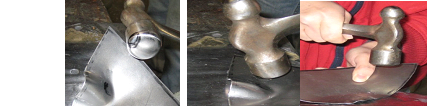
Figure 11: Tuck flattening
When hammering, we started inwards and went outwards; we also worked our way up the tuck. The hammer blows on the piece of metal should be very close to each other so that there is an even flattening effect on the tuck. It is also very important when hammering not to allow the tuck to return to its original place. Later on more tucks were made like shown below all around the metal piece and then hammered down like described above.
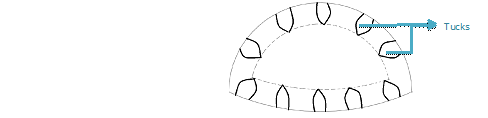
Figure 12: Tuck positioning
After some of the tucks we made were flattened out, the metal piece looks like in the pictures shown below.
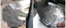
Figure 13: Flattened tucks
Once all the tucks were flattened out and the outer edges were shrunken, we had to thin out the center of the semi-circular metal piece in order to give it a dome shape. This was done by hammering gently on the outer edges of the metal piece and then applying stronger hammer blows at the center of the metal until we got the dome shape we were looking for.
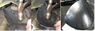
Figure 14: Hammering middle part of Piece B
After getting all the shoulder components a curvature, we made some holes in them using a nail puncher and a hammer. We also used a pair of pliers to remove small pieces of metal remaining in the hole.
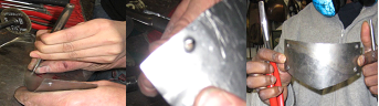
Figure 15: Hole making with a nail puncher
The holes were placed on the shoulder components as shown below. We did not use any measurements for the holes; we just approximated a distance from the outer edges of the shoulder parts. Holes were made in the shoulder components as shown in the table below.
| Part | Drawing |
|---|---|
| A | 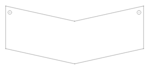 |
| B | 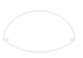 |
| C | 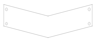 |
| D | 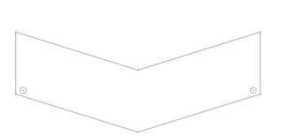 |
Figure 16: Hole position in shoulder components
Once the holes were made, we assembled the different parts together using copper rivets as in the pictures shown below. To assemble two pieces together, we first inserted a rivet in a hole and then we trimmed a portion of its length because it was too long. Once we got a reasonable length, we added a copper washer and hammered on the trimmed face of the rivet. As we hammered, the diameter of the rivet gradually increased and its longitudinal length decreases until the washer could not move and the shoulder parts were fastened together.
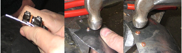
Figure 17: Assembly of shoulder components
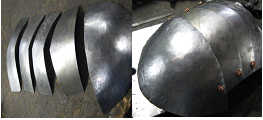
Figure 18: With copper rivets